Operational
Notes on
Visual-Aural
Radio Range & Associated Marker Beacons
These notes are taken from DCA Publication No. 19, Operational Notes on Visual-Aural Radio Range and Associated Marker Beacons, published in January 1953 - the time the Australian VAR system was commissioned into use.
The VAR network, consisting initially of 30 beacons established along the major air routes, replaced the twenty year old system of 33 Mc 'Lorenz' beacons. The higher frequency of the VAR system (120 Mc) eliminated the interference between beacons that was a problem with the 33 Mc beacons, as well as 'night' and 'skip' effects which could distort the signal. The VARs also offered four courses to the 33 Mc beacons' two courses. Distance along the airway was still marked by station passage of the VAR beacon, or of one of the associated Airways Marker Beacons - Distance Measuring Equipment (DME) was still a few years away.
1 - Introduction
The Visual-Aural Radio Range (VAR) is a short range radio aid to navigation which furnishes definite visual and aural track guidance for distances up to approximately 100 miles when flying at an altitude of 8-10,000 feet. The actual distance of usable reception from a range station is dependent upon en route terrain and altitude. Aural signals provide sector and station identification.
The range system operates in the Very High Frequency (VHF) band and is therefore normally free from atmospheric disturbances, "night" and "skip" effects. The line of sight propagation characteristics of VHF transmission limits the usability of the range to an area above the horizon of the transmitting station.
Two types of marker beacons are associated with the Visual-Aural Radio Range system; a "Fan" or Airway marker and a cone or "Z" marker. Marker beacons are situated at strategic locations on the VAR tracks to furnish accurate positional information to the aircraft. Each beacon emits a distinctive code to indicate its geographical position relative to the aerodrome. Normally, the signal radiated from the ground marker transmitter may be received to a height of about 20,000 feet.
Marker beacons operate in the VHF band but on a lower frequency than the VAR transmitting stations.
The aircraft VAR and marker receiving equipment provides visual and aural indication of the signals received from the ground VAR stations and marker beacon transmitters.
2 - V.A.R. Ground Stations
Click here to see the VAR ground station installation.
Range Tracks
The Visual-Aural Radio Range provides two visual and two aural tracks. The visual tracks may be set up on straight-through directions (180 degrees separation) or displaced from the straight-through condition according to operational requirements. The aural tracks are normally set up on straight-through directions.
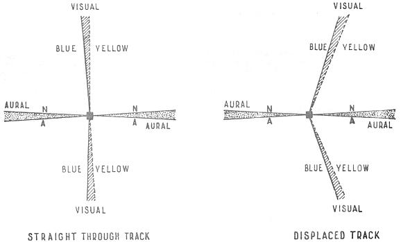
Visual Tracks
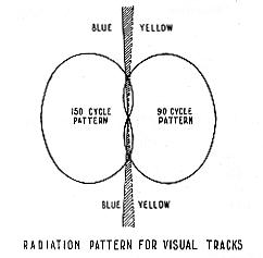
The visual tracks of the VAR are produced by the radiation of two overlapping patterns. One pattern is modulated at 150 c.p.s. and the other at 90 c.p.s. The sector in which the 150 cycle tone predominates is known as the blue sector and the sector in which the 90 cycle tone predominates is known as the yellow sector. The visual tracks are determined by the points of intersection of the two patterns. At these points the strength of the two tones is equal.
The two tones are interpreted in the aircraft receiving equipment and fed to the VAR visual indicator in the aircraft in such a manner that when the tones are equal the vertical pointer will remain centred and indicate "on track." Deviation of the aircraft into the 150 cycle pattern results in a proportionately larger amount of 150 cycle tone in the output of the receiver, which will cause the vertical pointer to move into the blue sector of the indicator.
Conversely, if the aircraft moves into the 90 cycle sector this tone will predominate and the vertical pointer will move into the yellow sector of the aircraft indicator.
In either case, the movement of the pointer will increase progressively with the deviation "off track" until full scale deflection to the left or right is reached at a point approximately 10 degrees "off track", a total of approximately 20 degrees for full scale right to full scale left, provided that the aircraft is within the usable range of the VAR station. The vertical pointer will remain deflected to full scale either blue or yellow for deviations greater than approximately 10 degrees "off track."
When crossing the visual track, there will be a continuous transition of the pointer from blue to yellow or vice versa. There will be no extended period of "on track" indication as in the case of aural ranges. In the case of range tracks being set up for other than straight-through directions the 150 cycle and 90 cycle patterns are not symmetrical so that the aircraft may deviate, for example, up to 8 degrees "off track" instead of 10 degrees, as stated above, to obtain a centre to full scale pointer deflection in the 90 cycle (yellow) sector, and 12 degrees deviation instead of 10 degrees would be required for full scale pointer deflection in the 150 cycle (blue) sector. The amount of asymmetry will depend upon the degree of displacement of the tracks from the straight-through alignment.
Aural Tracks
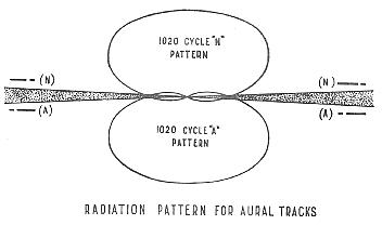
The aural tracks, like the visual tracks, are produced by the radiation of two overlapping patterns. The signal radiated to produce the aural patterns is modulated by a 1020 c.p.s. tone. One pattern is keyed by the Morse letter "A" and the other pattern by the Morse letter "N". These two Morse letters interlock to give a constant 1020 c.p.s. tone at the intersection of the two patterns.
When the aircraft is on the aural track a constant tone will be heard through the telephones connected to the aircraft VAR equipment; to one side of the track a predominance of the Morse letter "A" will be heard and on the other side the Morse letter "N" will predominate. The aural track (sector of constant tone) is approximately 1½-2 degrees in width.
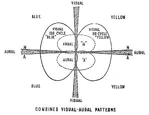
Combined Visual-Aural Tracks
Visual and aural tracks are radiated simultaneously to produce a composite radiation pattern.
Alignment of Tracks
The tracks of visual-aural radio ranges installed in Australia are orientated so that the visual tracks are aligned along the major airways. At some aerodromes where more than two lanes of approach are required, the aural track is used for airways navigational guidance.
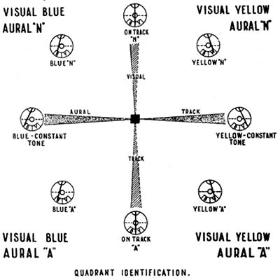
In the ease of visual tracks aligned on the north-south airways, the yellow sector (90 cycles) lies to the east of the station and the blue sector (150 cycles) lies to the west.
For the aural tracks the Morse letter "A" will be heard to the south of the station and the Morse letter "N" to the north.
On the east-west airways the visual and aural signals will have the same orientation as the north-south airway tracks but rotated 90 degrees clockwise.
Reference should be made to the current issue of ANFAC for details of visual and aural track directions. In all cases the bearings given are in magnetic and towards the range station.
Quadrant Identification
In addition to providing aural tracks, the aural signal serves as a positive means of orientation. Receipt of the aural signal "A" or "N" together with a blue or yellow visual indication provides immediate identification of the quadrant in which the aircraft is flying, since the combination of a colour and a letter in any one quadrant is not repeated in any other quadrant.
The orientation for each visual-aural radio range station in Australia is shown in the current issue of ANFAC.
Carrier Frequency
Visual-Aural radio ranges in Australia operate in the frequency band 112-118 Mc. The frequency and channel for each range station is given in ANFAC.
Station Identification
Identification of each range station is given at 30 second intervals by alternately keying the two aural patterns with the station’s call letters. During these short periods the aural track indications are not available.
Over-the-Top Indications
When flying a visual track directly over the top of a range station, the visual track indicating pointer will momentarily sweep from side to side and in the telephones the aural signal will be heard to change from "A" to ‘N" or vice versa depending upon the direction from which the station is approached.
The "Over-the-Top" indication when approaching the station on the aural track is marked by a sharp cone of silence in the telephones accompanied by the movement of the visual pointer from one sector to the other.
This "change over" area may be used to indicate the passage of the aircraft over a range station not equipped with a marker beacon.
Simultaneous Voice Transmission
Simultaneous voice modulation may be superimposed on the range station transmission without interfering with the range signals. A voice-range filter is required in the aircraft equipment to attenuate the 1020 c.p.s. aural range signal during periods of voice reception. Simultaneous voice transmission is not yet in use on VAR ranges in Australia.
Monitoring
The present VAR monitoring system provides for an alarm when any one of the following fault conditions occur:-
(a) Visual System:
(i) Track deviation in excess of ± 30.
(ii)
Failure of sideband radiation.
(iii) Decrease in transmitter power output
to approximately one half.
(b)
Aural System:
(i) Failure of A-N (Track) keying.
(ii) Failure or mutilation
of station identification, (this characteristic is checked at least every 30 minutes
by duty operator).
(iii) Track deviation in excess of ± 3o at stations
where the aural Track is used as a route guide.
3 - Marker Beacons
Cone or "Z" Markers
The cone or "C marker is in most instances located close to the range station so that the aircraft’s position over the station may be accurately and positively identified.
"Z" markers operate on a frequency of 75 Mc. and are modulated by a 3,000 c.p.s. tone. Positive identification is provided by keying the 3,000 cycle tone with the Morse letter "Z".
The radiated pattern is essentially conical in shape and can be received for approximately 20 seconds at an altitude of 2,000 feet above the transmitter while flying at 120 knots. The signal may normally be received to a height of about 20,000 feet above the transmitter.
The "Z" marker signal is received by the airborne marker receiver and presented visually by a light in the marker indicator installed on the instrument panel of the aircraft and can also be heard in the telephones connected to the marker equipment.
Fan or Airway Markers
Fan or airway markers are located at strategic points along the airway to enable the aircraft’s position from the range station to be accurately determined and to provide fixed reference points for aircraft holding manoeuvres.
Fan markers radiate a signal on the same frequency as the "Z" markers (75 Mc.) and are modulated by a 3,000 c.p.s. tone keyed by the Morse symbol identifying the location at which the markers are installed.
The radiation pattern of the fan marker is, as the name implies, fan-shaped. The major axis is placed at right angles to the range track and the minor axis along the range track. The signal in the latter direction can be received for approximately 35 seconds at an altitude of 5,000 feet when flying along the range track at 120 knots. The signal may normally be received to a height of about 20,000 feet above the marker transmitter.
The fan marker signal is received on the airborne marker receiver and presented visually on a lamp in the marker indicator installed on the instrument panel of the aircraft and can be heard in the telephone.
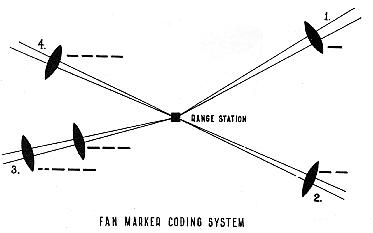
Fan Marker Coding System
Identification signals are usually coded in accordance with the following arrangement. Beginning at true north and proceeding in a clockwise direction, the range tracks are numbered 1, 2, 3 and 4. A marker on track No 1 would be keyed to emit single dashes. A marker on track No 2 would be keyed to emit groups of two dashes; on track No 3 groups of three dashes; and on track No 4 groups of four dashes.
Should there be two fan markers on a range track, the regular coding of the marker farthest out from the range station would be preceded by ". ."; thus the coding of the second marker out from the range station on track No 3 track would be ". . - - -". At a few locations non-standard coding may he ad opted to avoid confusion between markers on closely adjacent range tracks.
Location and Identification of Marker Beacons
Reference should be made to ANFAC for information as to the geographical positions and identification of "cone" and "fan" marker beacons installed at each VAR range track.
4 - Airborne Equipment
Visual-Aural Radio Range Receiving Equipment
General
The
airborne receiving equipment used with the visual-aural range is composed of four
basic components:-
(a) Receiver.
(b) Control panel.
(c) Cross pointer
indicator.
(d) Aerial.
Receiver
The receiver unit feeds the signal received from the VAR ground transmitter through conventional superheterodyne circuits to the telephones for reception of the aural range signals and to a special section of the receiver which compares the relative signal strengths of the visual 90 c.p.s. (yellow) and 150 c.p.s. (blue) signals. The signal is then conveyed to the vertical pointer of the cross pointer indicator which remains centred if the two signals are equal (on track) or deflects to the blue or yellow sector, depending upon which signal is predominating. The amount of deflection into the blue or yellow sector of the indicator depends on the distance "off track".
The visual section of the receiver contains components to reduce the sensitivity of the pointer movement to unwanted fluctuations of short duration such as those caused by reflections. Without this damping circuit the fluctuations of the needle would lead to unnecessary corrections of the aircraft heading.
Typical VAR airborne receivers in use in Australia have provision for reception of visual-aural ranges on any one of six channels.
Control Panel
Power
to the receiving equipment is controlled by the "On-Off" switch. Range
station frequencies are selected by means of a semi-rotary channel selector switch;
channels being designated by letters. Channels "A", "B", "C",
"D" and "E" have been assigned to VAR ranges in Australia.
The channel and frequency of all VAR stations is shown in ANFAC. Channel "Z"
in the case of the equipment being described is reserved for use with the localizer
element of the instrument landing system.
The audio volume control incorporated
in the VAR control panel is a master control for varying the audio output level
from the receiver. As with other equipments, the recommended practice is to set
the selector jack-box control for maximum output and then advance the master control
on the VAR control panel to a comfortable listening level.
Cross Pointer Indicator
The cross pointer indicator, which is situated in a suitable position on the aircraft instrument panel, comprises two indicator pointers, one vertical and the other horizontal. The vertical pointer is pivoted at the top of the dial and moves in a pendulum fashion to the left or right. This pointer responds to changes in the aircraft’s position relative to the VAR or localizer track. Viewing the indicator from the front, the bottom of the dial is divided into yellow and blue sectors; the yellow sector is on the right of the instrument and the blue sector to the left.
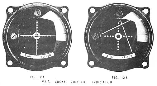
The horizontal pointer is pivoted on the left hand side of the instrument and swings up. The pointer (used for glide slope indications on an instrument landing system) has, in the instrument illustrated, been modified to function as a usability and warning indicator when used with the Australian Visual-Aural Radio Ranges.
The
tip of the horizontal pointer sweeps through a scale divided into three sections.
The first is a small red section in which the tip of the pointer rests when:-
(a) Power is not applied to the VAR receiver.
(b) The receiving equipment
is defective.
(c) The aircraft is outside the coverage area of the VAR station
selected.
(d) The VAR station is not transmitting.
The second section of the scale, to the white dividing line, is coloured green and when the pointer is in this section it is an indication that the aircraft is not sufficiently close to the VAR station to use the equipment for navigation purposes.
The green sector above the white line is marked "USE" and when the pointer tip is in this sector it is an indication that the aircraft is within the coverage area of the selected range station.
Note: As excessive aircraft electrical noise can also deflect the horizontal pointer into the "USE" sector, even in the absence of a range signal, it is important to check for clear reception of the range aural signal at frequent intervals.
Fluctuation of the track and usability pointers can be expected when taxying in some areas of an aerodrome due to extraneous electrical interference and shielding from buildings.
The centre part of the indicator scale is marked with a target circle and four dots each radiating vertically and horizontally from the target circle. These markings serve to divide the instrument scale into equal spaces. The peripheral line of the centre target circle is regarded as the first dot position, making a scale of five dots from the centre position of the pointer to full scale blue or yellow.
Aerial
The aerial for the VAR receiving equipment is specially shaped to reduce drag and to provide uniform omni-directional reception. In most cases the VAR aerial is mounted on the top of the fuselage in the foremost position.
Voice-Range Filters
Some aircraft installations are fitted with voice-range filters and associated switching components for use with overseas VAR and localizer stations employing simultaneous voice transmission. The filter is switched into circuit by a switch which can select any of the following functions:-
(a)
Reception of the range aural (1020 c.p.s.) signal only and excluding the voice
signal - "RANGE" position of the filter switch.
(b) Reception of
voice signals only and excluding the aural "range" signal — "VOICE"
position of the
filter switch.
(c) Simultaneous reception of range and
voice signals — "BOTH" position of the filter switch.
Marker Receiving Equipment
The
marker receiving installation used with the 75 Mc. ground marker beacons comprises
three basic elements:-
(a) Receiver.
(b) Indicator.
(a) Aerial.
Receiver
The receiver unit, which is fixed-tuned to the frequency of 75 Mc., feeds the signal received from the marker transmitter through conventional superheterodyne circuits to the headset for aural reception of the modulation tones and to the visual circuits where the modulation tones are fed through special filters to the indicating lights. The filters allow the signal to actuate only the light associated with the one modulation tone. For example the blue light is actuated by only a modulation tone of 400 c.p.s., the amber light by a tone of 1,300 c.p.s. and the white light by a tone of 3,000 c.p.s. Thus markers may be identified visually as well as aurally.
Indicator
Three lights are provided, blue, amber and white, which are actuated by the 400 c.p.s., 1,300 c.p.s. and 3,000 c.p.s. modulation tones respectively. As the modulation tones identify the type of marker, the lights are designated in the following manner:-
BLUE
(400 c.p.s. TONE) — "OUTER" (MARKER FOR I.L.S.)
AMBER (1,300
c.p.s.) — "MIDDLE" (MARKER FOR I.L.S.)
WHITE (3,000 c.p.s.
TONE) — "AIRWAY" AND "Z" (ALSO INNER MARKER FOR I.L.S.)
A "HI-LO" switch allows a choice of two sensitivity settings of the marker receiver. When the switch is in the "HI" position, the receiver is in its most sensitive condition and it is in this position that equipment is normally operated. Changing the switch to the "LO" sensitivity position decreases, by approximately one half, the time that the signal may be received.
A "day-nite" switch allows the lamp brilliance to be adjusted to suit individual requirements. Normally the switch is placed in the "day" position for flights in daylight and "nite" for night flying.
The marker receiver is not normally provided with a separate audio volume control; adjustment of level is normally made on the volume control in the selector box.
Aerial
The marker beacon receiver aerial is in all cases mounted on the underside of the fuselage or wings of the aircraft in a position clear of all other aerials and obstructions. In some aircraft an open wire approximately 80 inches in length is used, whilst other installations use an aerial recessed flush with the skin of the aircraft.
5 - Flying the Visual-Aural Radio Range and Marker System
Having adjusted the airborne equipment controls and noted the indication on the vertical (track) pointer, a check should be made on the aural signal to establish whether an "A" or "N" is being received. The of visual colour (blue or yellow) as shown on the vertical pointer and the aural signal will then establish in which quadrant the aircraft is flying. The aircraft heading can now be changed until the vertical pointer is steady in the central position, indicating that the aircraft is then flying along the range track. As the aircraft approaches the range station the vertical pointer will become more sensitive to changes in the aircraft heading.
NOTE: REGARDLESS OF THE POSITION OR HEADING OF THE AIECRAFT THE VERTICAL POINTER WILL ALWAYS BE DEFLECTED IN THAT COLOUR AREA IN WHICH THE AIRCRAFT IS FLYING.
As the aircraft approaches the range station on the visual track, listen for the change from "A" to "N" or vice versa, and observe a sweeping movement of the vertical pointer indicating that the aircraft is "Over-the-Top". For an approach on the aural tracks, identify the passage of the aircraft over the station by a sharp null in the range signal and a change in the vertical pointer from one sector to another.
Typical of aids operating in the VHF band, VAR range signals are affected by terrain in close proximity to the range site. A range station situated in an area of flat terrain will produce a perfectly steady indication. On the other hand, a site adjacent to high or uneven terrain will cause some fluctuations of the vertical pointer. These fluctuations are not apparent in the aural signal due to the relative insensitivity of the human ear. When these fluctuations are encountered it is preferable to average out the fluctuations by steering the aircraft on a gyro heading.
When flying along a range track provided with markers, the marker signal will be heard in the telephones when the aircraft is over the marker transmitter and the appropriate light on the marker indicator will flash in synchronism with the keyed modulation tone. With some types of airborne equipment the marker aural signal may be heard for a short time before the light is visible and for a short time after it has extinguished.
NOTE: THE VAR SYSTEM CANNOT BE SATISFACTORILY USED FOR ‘OFF COURSE’ TRACKING; THEREFORE THIS TYPE OF NAVIGATION SHOULD NOT BE ATTEMPTED.
-oOo-
Click here to see the VAR ground installation
Click here to see Instrument Approach Chart for VAR Approaches at
Back
to the main Communications
& Navigation index
If
this page appears without menu bars at top and left, click
here